Electrostatic Desalting HV Inlet Device

System role

One continuous high-voltage path, three coordinated interfaces

The feedthrough is not a generic transformer accessory. It must be engineered together with the transformer termination, the vessel nozzle or sleeve, and the internal electrode connection.

Transformer output

Connection type, voltage waveform and insulation coordination are confirmed for the selected power system.

Feedthrough boundary

Insulation, mechanical support and sealing are coordinated at the vessel electrical entry.

Electrode system

The internal connection delivers high voltage to the electrode grid used to establish the treatment field.

Two structural forms

Select the arrangement from the actual vessel and retrofit conditions

The two forms serve the same electrical function but are not interchangeable without checking the complete mechanical and electrical interface.

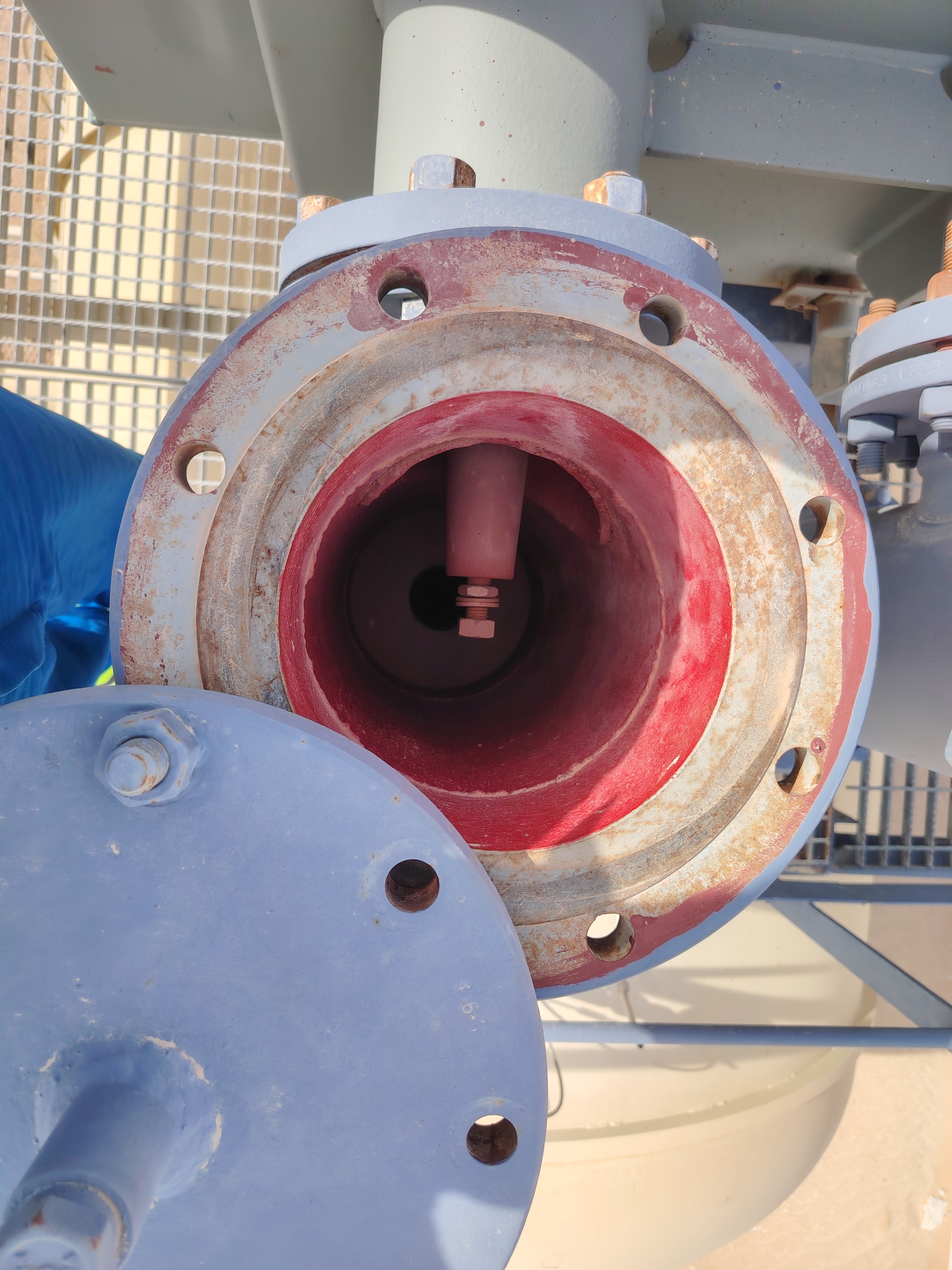
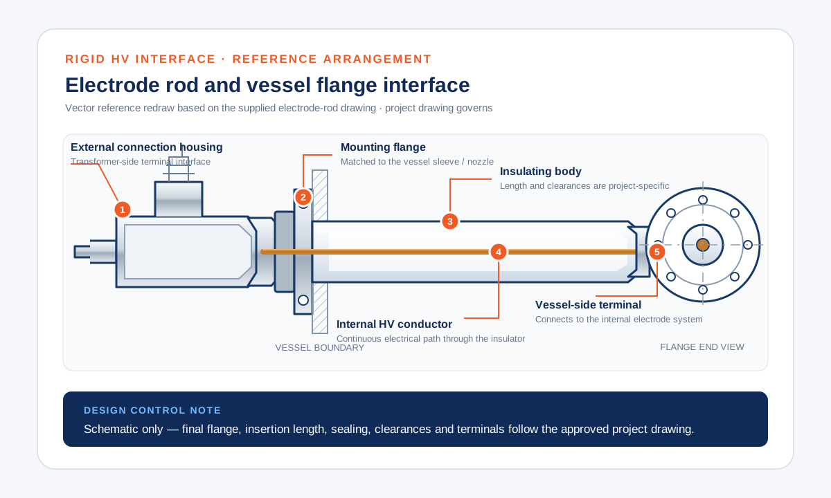
Non-dimensional rigid electrode rod and vessel flange interface diagram

Rigid cross-sleeve / electrode-rod arrangement

A rigid insulated electrode rod passes through the vessel sleeve or flange and connects to the internal electrode system. The flange, insertion length, clearances and terminal geometry are matched to the vessel drawing.

Rigid interfaceFlange matchedDrawing controlled
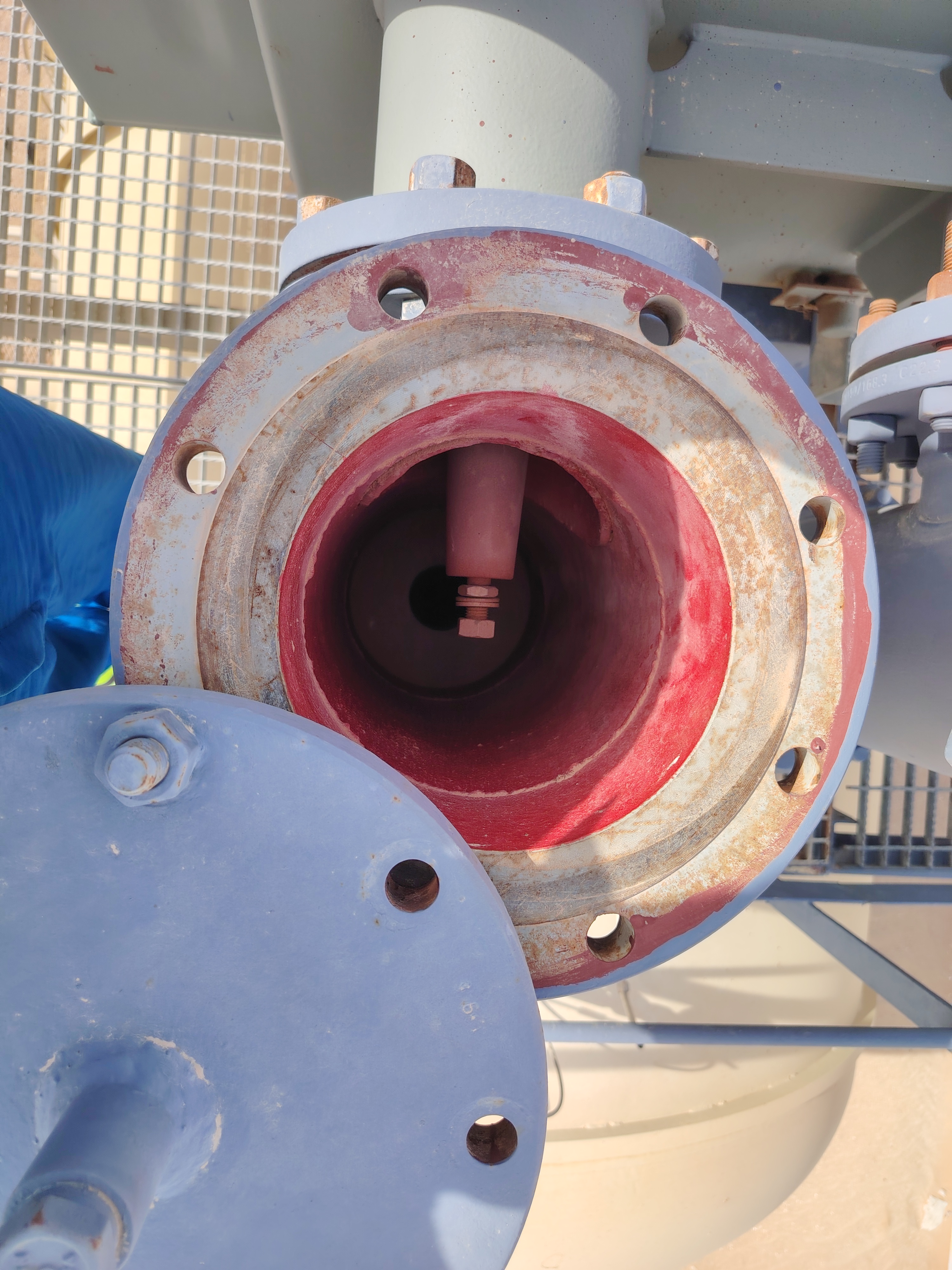
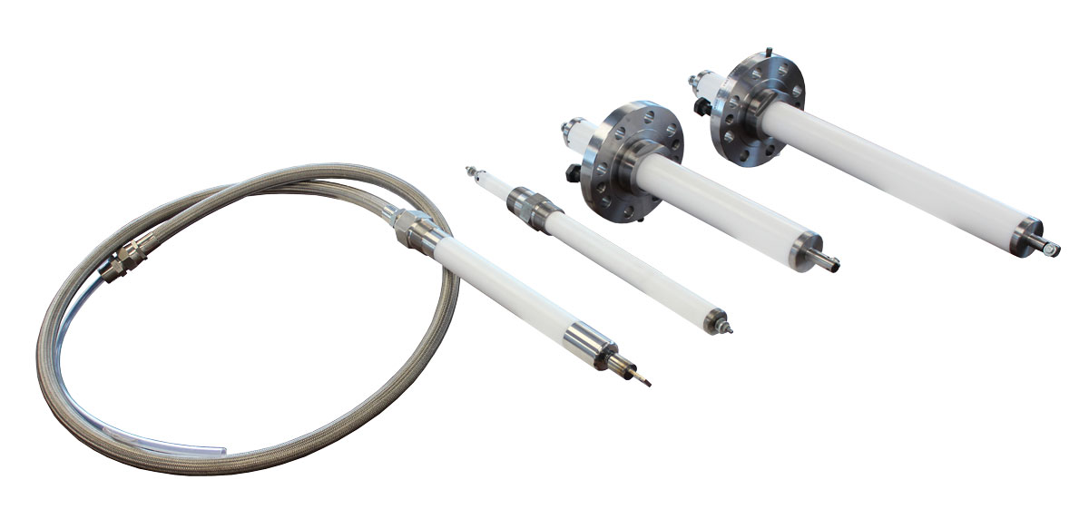
Flexible high-voltage cable and electrode rod arrangement installed on site

Flexible high-voltage introduction assembly

A special high-voltage cable, protective metal hose and insulated plug-in connection bridge the transformer output and vessel electrode rod. Routing, bend allowance and termination details are reviewed as one assembly.

Flexible routingProtected cableMatched termination
Project configuration

Six inputs define a correct replacement or new-build assembly

Ratings and dimensions are confirmed from the project data sheet, approved drawings and site information rather than presented as universal values.

01

Electrical duty

Waveform, voltage definition, current, frequency or pulse duty, channel count and insulation coordination.

02

Vessel interface

Nozzle or sleeve size, flange standard, bolt pattern, insertion direction and available installation clearance.

03

Electrode connection

Internal electrode layout, connection point, conductor geometry and required mechanical support.

04

Transformer termination

Output terminal type, cable or rigid connection, separation distance and compatible termination hardware.

05

Process and site

Design pressure and temperature, crude and wash-water conditions, area classification and ambient exposure.

06

Inspection scope

Approved drawing review, dimensional checks, insulation and sealing tests, documentation and shipment protection.

Maintenance reference

Source-based views clarify the equipment interfaces

These views are extracted from our high-voltage entry-device maintenance material and retain the actual equipment topology. They support interface review but do not replace verified dimensions and approved drawings.

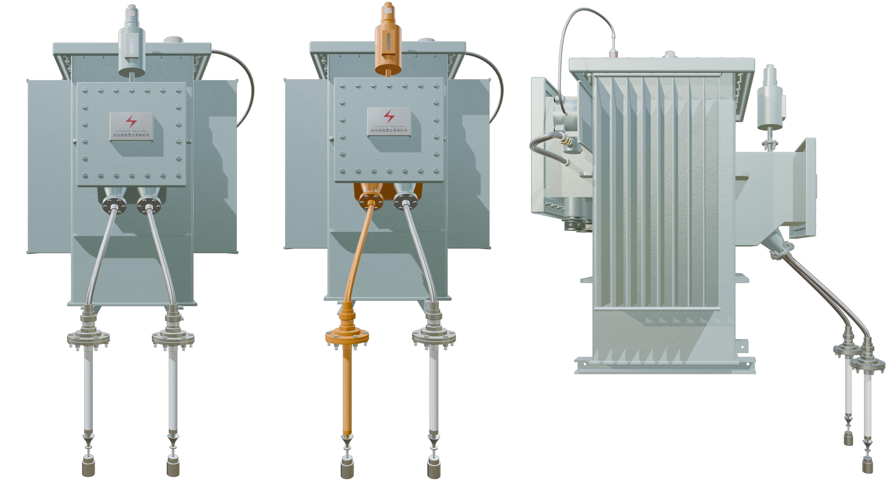
Front and side maintenance views of desalter transformer high-voltage entry connections
System arrangement

Front and side views show the transformer terminal box, flexible enclosures and vessel-side entry rods as one connected system.

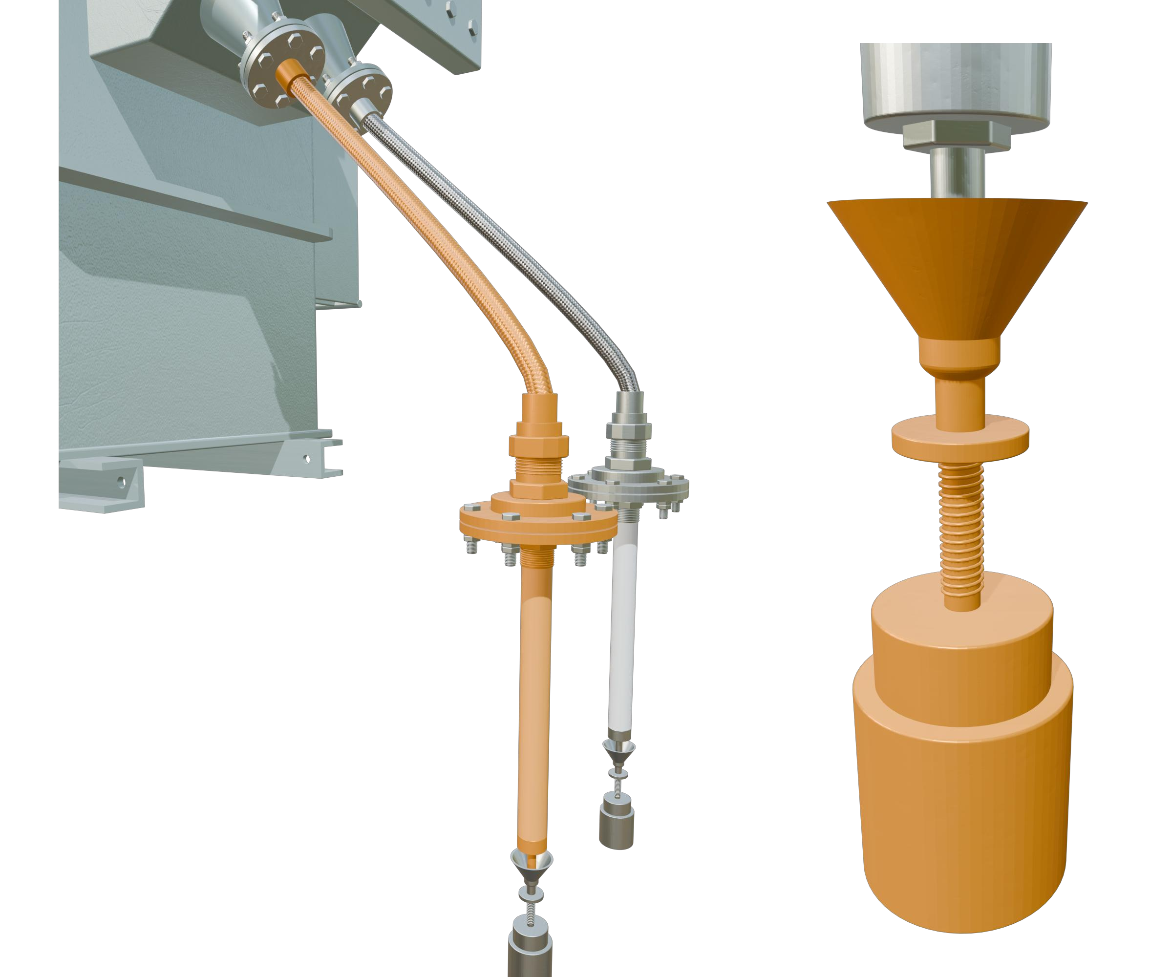
Maintenance detail of flexible enclosure, vessel flange and spring-loaded internal contact
Connection detail

Highlights the flexible enclosure, vessel flange, entry rod and spring-loaded internal contact without publishing project dimensions.

Engineering note: the views explain functional relationships only. Final material, dimensions, pressure boundary, electrical rating and hazardous-area requirements must be confirmed for each project.

Send the interface data before replacement selection

Recommended inputs: existing drawings and nameplates, vessel flange dimensions, transformer output details, electrode connection, operating conditions and clear site photographs.

Discuss your project →