Nitrogen gas space
A nitrogen space above the oil limits direct exposure to ambient air and accommodates oil-volume changes. Gas volume, charging pressure and operating pressure range are coordinated with the tank design.

A sealed tank combines an oil-immersed active part with a nitrogen gas space above the liquid. Nitrogen cushioning, tank strength, pressure relief and rapid pressure protection are considered together for projects that require reliable oil preservation and internal pressure-risk mitigation.
The technical concept is intended for 35–110 kV applications. Power rating, voltage ratio, temperature rise and dimensions are defined by the project specification.
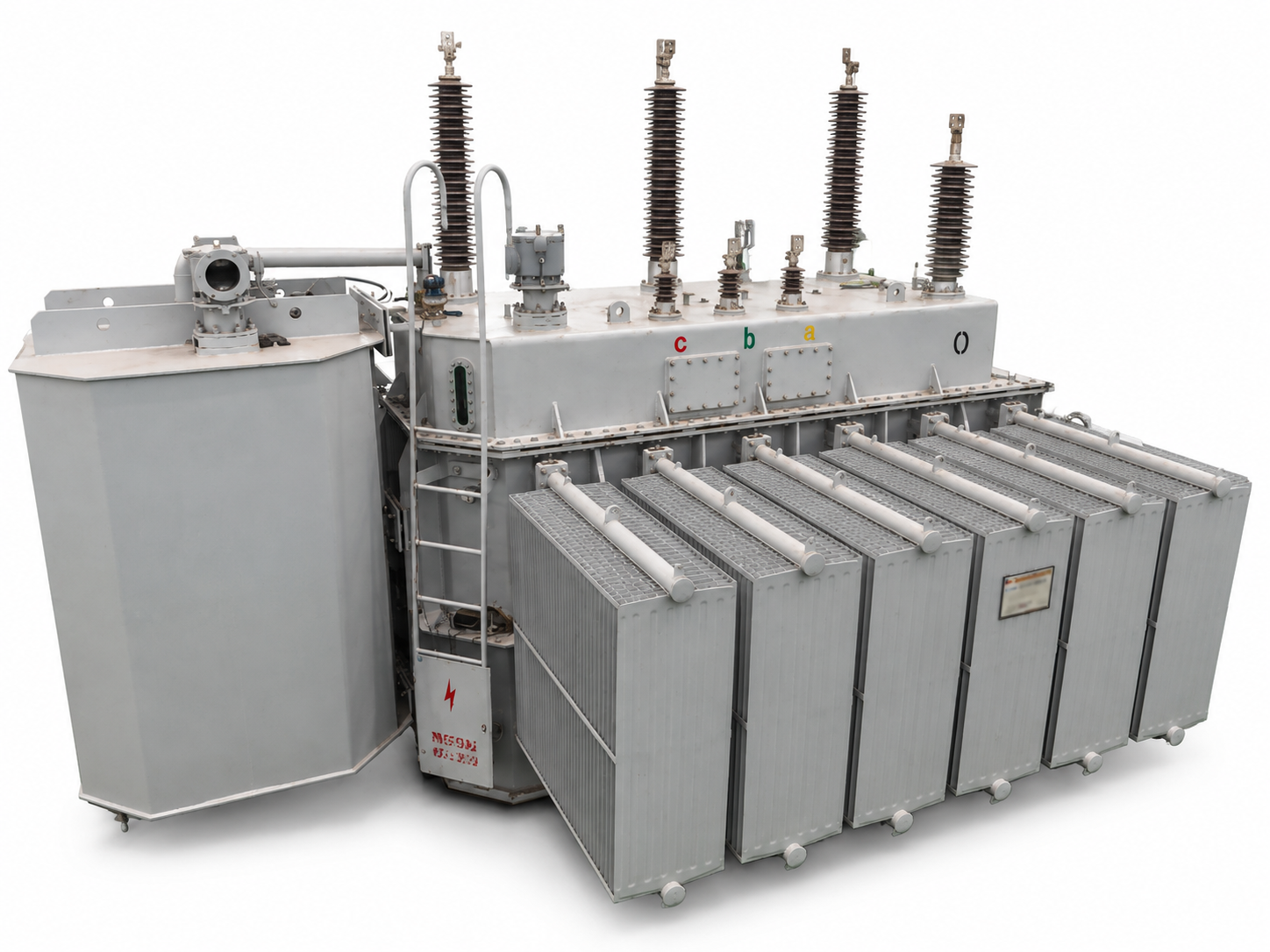
A nitrogen space above the oil limits direct exposure to ambient air and accommodates oil-volume changes. Gas volume, charging pressure and operating pressure range are coordinated with the tank design.
Tank walls, reinforcement, welds, pressure relief and rapid fault clearance work together to reduce tank-rupture risk. Performance is subject to verification for the specific design.
The reference arrangement uses extended dry-type bushings with main connections below the specified oil level. Insulation coordination considers the oil–gas interface.
Project options include pressure relief, a gas-space rapid pressure rise relay, oil and winding temperature monitoring, oil-level indication, pressure/vacuum indication and alarm/trip contacts.
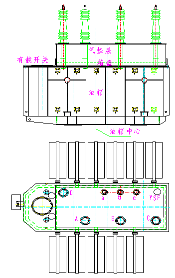
The reference design uses a barrel-type tank without a main conservator. A welded box above the main cover, outside the tap-changer area, contains oil in its lower portion and nitrogen above it to accommodate oil-volume changes.
Dry-type bushings mount on the box cover. Extended tails bring the high-voltage connections below the oil surface, while the reference on-load tap changer is oil immersed.
A pressure wave from an internal fault travels through the oil toward the nitrogen layer. The compressible gas space provides cushioning, with a broad oil–gas interface in this design. Tank reinforcement, pressure relief and rapid protection work together.
Nitrogen separates the oil from ambient air. Fault performance depends on fault energy, tank strength and coordinated protection.
The reference design uses integrally formed wall panels to reduce welded area. Wall thickness is stated as 1.2 times that of its conventional comparison design, with closer reinforcement spacing near the upper long sides.
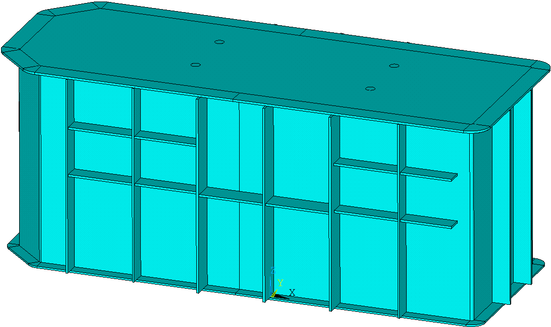
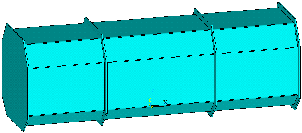
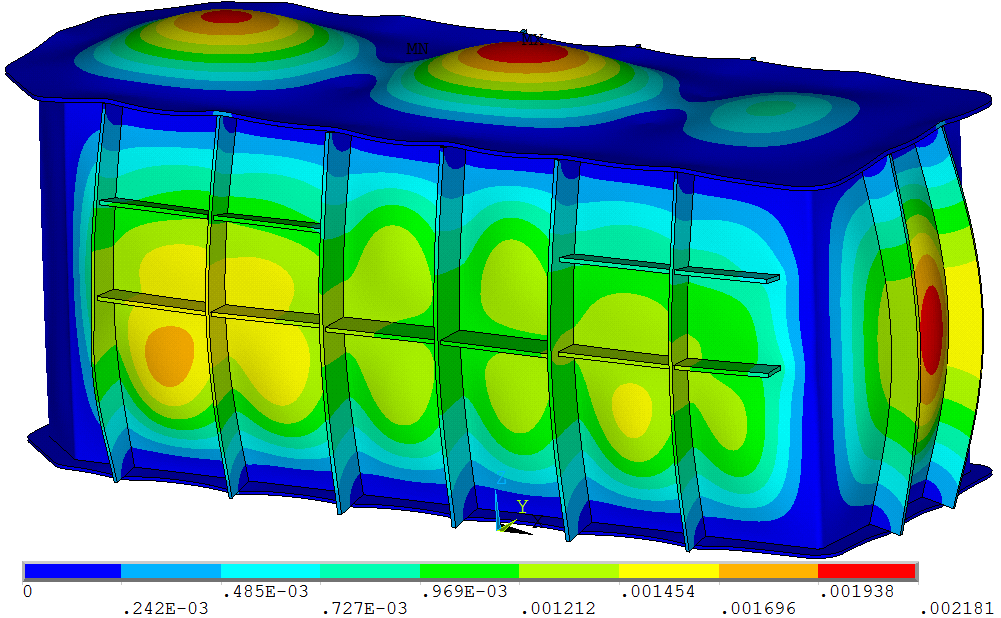
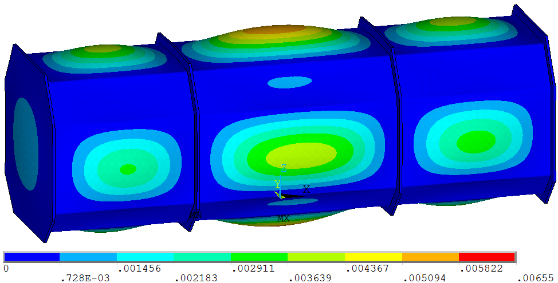
Original design and simulation images. The 1.2× thickness ratio applies to the reference design. Complete loads, material properties, boundary conditions and acceptance limits are not given in the presentation; these images do not establish a certified tank-rupture pressure.
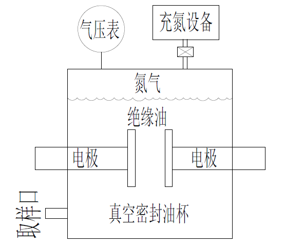
The presentation describes a study with upper conditions of 165 kPa nitrogen pressure and 105°C oil-surface temperature, evaluating power-frequency breakdown voltage at approximately 0–16% reported nitrogen solubility.
| Nitrogen solubility (source wording) | Mean breakdown voltage |
|---|---|
| 0% | 66 kV |
| 5.24% | 65.6 kV |
| 10.87% | 65 kV |
| 15.92% | 64.7 kV |
The reported means range from 66 to 64.7 kV. For these test conditions, the presentation concludes that dissolved nitrogen has a small effect on oil dielectric strength.
Source: p.16. Full test method, electrode gap, sample count and solubility definition are not stated. These are oil-sample results, not transformer insulation ratings or guaranteed operating temperature/pressure limits.
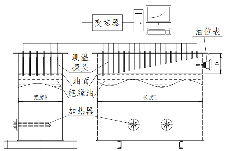
The reported test found a warmer nitrogen layer near the oil surface and a cooler layer near the cover. Under the stated rated-load condition, the top gas layer was approximately 15°C cooler than the oil surface. This informs assessment of the environment around cover-mounted bushing, valve and instrument seals.
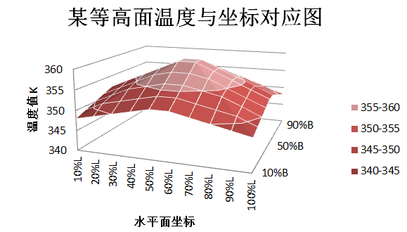
The reference design also increases the number of seal fasteners. Temperature distribution, flange design, seal materials and tightening procedures are considered together.
The approximate 15°C difference is a reported test observation, not a fixed difference or seal-life guarantee for every transformer.
The reference scheme uses a gas-space rapid pressure rise relay for fast internal-fault pressure detection in place of its conventional severe-gas-fault protection arrangement. Mounted on the gas-box cover, it responds to the rate of pressure change. Its role differs from a pressure-relief device that opens at its specified pressure condition.
| Device | Function |
|---|---|
| Pressure-relief device | Relieves internal pressure at the specified device condition |
| Gas-space rapid pressure rise relay | Detects rapid gas-pressure changes and initiates a protection signal |
| Oil temperature indicator | Monitors top-oil temperature, with specified alarm/trip interfaces |
| Winding temperature indicator | Provides winding-temperature monitoring or indication; method depends on configuration |
| Oil-level indicator | Indicates liquid level for inspection and specified alarms |
| Pressure/vacuum gauge | Indicates gas-space pressure for assessment alongside temperature |
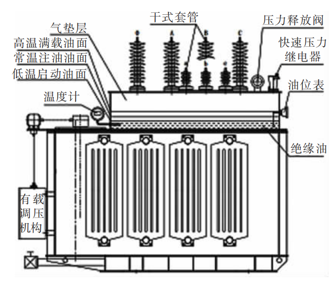
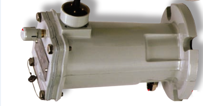
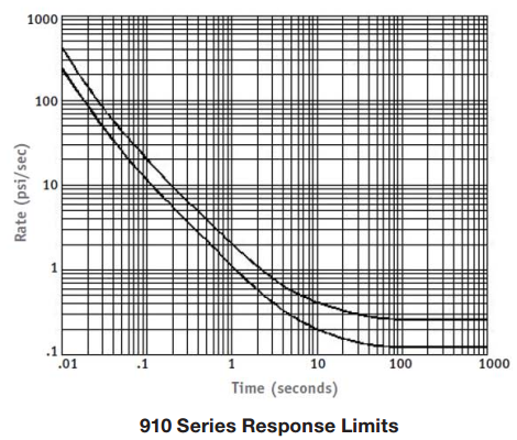
Images and curves describe the reference scheme; brands, models and settings are project specific. The p.19 calibration certificate concerns one relay, not hazardous-area certification of the complete transformer. Applicable calibration documents may be reviewed during technical clarification.
The reference process values below support engineering discussion. Site work requires the approved model-specific installation instructions and qualified personnel. The presentation does not fully define gauge versus absolute pressure or all applicable temperature conditions.
| Stage | Source values | Engineering context |
|---|---|---|
| Vacuum treatment and oil filling | 133 Pa for 12 h | Source specifies covering the active part and filling above the main tank top; approved oil level and vacuum capability are model specific |
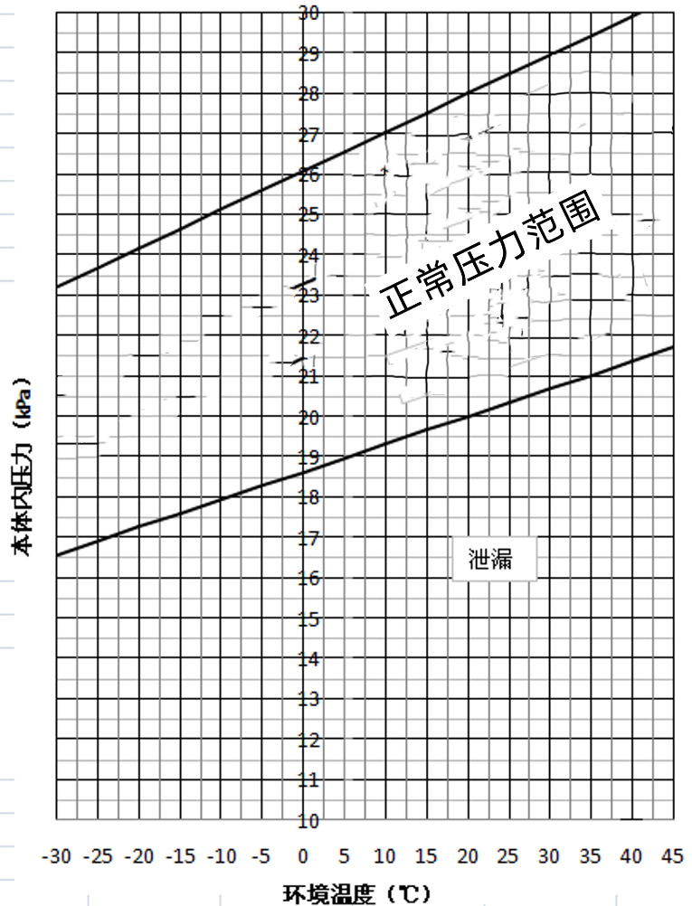
| Nitrogen charging and sealing | Purity ≥99.99%; 0.02–0.03 MPa | Source calls for adjustment against its ambient-temperature/pressure curve, then sealing the charging connection |
| Standing and observation | 8 h | Record gas pressure alongside ambient temperature; investigate sealing when readings leave the normal band |
Gas pressure changes with temperature. A single pressure reading is insufficient to diagnose a leak. The source curve illustrates the relationship used for charging adjustment and subsequent observation.
Source: p.20. This reference image is not a setting curve for other models. Project documentation must specify the applicable model, units and pressure reference.
Pages 6–9 compare four approaches. The table retains the source comparison to explain where this design fits; suitability depends on the actual equipment and project.
| Reference route | Insulation and accessories described in the source |
|---|---|
| SF₆ gas insulated | SF₆ main insulation, dry-type bushings and gas-type tap changer |
| Dry type | Dry active part; reference arrangement without bushings and with a dry-air on-load tap changer |
| High-fire-point liquid | Natural ester, oil-paper bushings and an oil-immersed on-load tap changer in the reference example |
| Nitrogen-sealed oil immersed | Conventional oil below, nitrogen above, dry-type bushings and an oil-immersed on-load tap changer |
The product concept covers 35–110 kV applications (p.22). These accessory combinations are source examples, not mandatory configurations for every product in each category.
See the relationship between the nitrogen space, insulating oil and active part. Rotate, zoom and switch between external, transparent and exploded views.
The exterior follows the product photographs and reference. The large side enclosure is represented externally; its function requires assembly-drawing confirmation. Internal geometry, proportions and exploded positions are illustrative, not manufacturing dimensions or a dismantling procedure. Fluid colors are for identification only. Open 3D viewer separately
| Application voltage range | 35–110 kV; final voltage combination by agreement |
|---|---|
| Power, frequency and phase | Selected for the network and load |
| Oil preservation | Sealed tank with nitrogen gas space; conservator-free reference arrangement |
| Insulating liquid | Conventional transformer oil in the reference design; esters require separate evaluation |
| Cooling and tap changing | Selected for losses, ambient conditions, temperature rise and regulation duty |
| Thermal performance | Top-oil, average winding and hot-spot limits defined separately |
| Monitoring and protection | Project-specific pressure, temperature, oil level and alarm/trip interfaces |
| Testing and delivery | Standards, test schedule, weight and dimensions by technical agreement |
No. This is an oil-immersed transformer. Nitrogen occupies the space above the oil, while the active part and main connections remain below the specified oil level.
No. This concept addresses oil preservation and internal pressure protection. External explosive gas or dust atmospheres require a separate assessment of area classification, equipment suitability and certification.
Nitrogen cushioning and coordinated protection reduce risk. Performance must be defined within specified fault conditions and verified test limits; no unconditional fire-free or rupture-free claim is made.
Permissible temperatures depend on the insulation system, cooling design and service-life requirements. Fire point, insulation thermal class and operating temperature rise are different parameters.
Share rated power, primary and secondary voltages, tap range, vector group, impedance, ambient conditions, altitude, installation location, loss and temperature-rise limits, monitoring interfaces and required tests.
Related products: Power transformers · Oil-immersed transformers